Your File Stays on Your Device: Parsing PNG, PDF, DXF, and DWG in the Browser to Build a 3D Layout
Part 05 turned a hand-prepared layout into 3D with Three.js. This one handles the plan you already have. It might be a screenshot, a PDF, or a DXF or DWG file from your architect.
Our 3D layout lab accepts all four formats. Parsing, wall extraction, and scaling all happen in your browser. The file is not sent to a server.
This article covers three things honestly. First, the path each format takes. Second, how walls are extracted. Third, what we cannot do. It ends with the pitfalls we hit, plus three bugs we found during a review and fixed the same day.
The short version
Walls: yes, with conditions. For images and PDFs, we only detect horizontal and vertical walls. For DXF and DWG, we use layer names plus parallel-line pairing.
Doors and windows: no. None of the four formats detects doors or windows. You cannot place them by hand either.
Scale: If a DXF or DWG file declares mm, cm, or m, the tool uses that unit. Otherwise it guesses from the drawing size. For images and PDFs, we suggest clicking a wall of known length.
1. Why everything runs in the browser
A floor plan is personal. It shows how many rooms you have and where the doors are.
So parsing happens in your browser, and the file is not sent to a server. The tool page also says "Files stay on your device."
This approach has two costs:
The parsers must download to your device. The PDF and DWG parsers download only when you pick that file type. The DWG parser is large; numbers follow below.
Your device does the work. A slower device means a longer wait.
There is one more requirement: the 3D scene must start. The scene uses WebGL, the browser's interface for drawing 3D with the graphics card. Without WebGL, uploads are not parsed. The page shows a notice card instead.
2. Four formats, four paths
Some terms first:
CAD file: a drawing made in design software. It stores lines and text, not pixels.
DXF and DWG: two common CAD file formats. DXF comes in text and binary forms.
Layer: CAD files group lines by purpose, such as walls, dimensions, or furniture. Each group is a layer.
Main thread: the thread that runs the page's UI. Long work here freezes the page.
Web Worker: a background thread. Work placed there does not occupy the main thread.
WASM (WebAssembly): compiled code that browsers can run. It lets a C library run inside a web page.
| Format | Where it runs | How it is read | What comes in | Where scale comes from |
|---|---|---|---|---|
| PNG / JPG / WebP | Main thread | Long side scaled to 960 px, then scanned for dark lines | Horizontal and vertical walls | You click a wall and type its length |
| Converted to an image with pdf.js (pdf.js has its own worker); then same as PNG | Page 1 only, rendered to about 2000 px on the long side, then the PNG path | Same as PNG | Same as PNG | |
| DXF | Main thread, our own TypeScript | Reads the unit field and the lines of a text DXF | Lines, lightweight polylines, text | File unit; otherwise drawing size |
| DWG | Web Worker + WASM (LibreDWG) reads the file; walls are built back on the main thread | WASM reads the file and returns plain data | Lines, polylines (including 2D and 3D polylines), text | Same as DXF |
A few details:
PDFs always become images first. We do not extract vectors, even if the PDF has them. Only page 1 is read. A multi-page PDF shows a "Read page 1 only" note.
DXF must be text (ASCII). The parser reads one code line, then one value line. Binary DXF should therefore fail. We inferred this from the code; we did not test it.
DXF and DWG share one wall builder. After loading, both follow identical wall rules. Changing unit or layers for a DWG reruns the builder, not the WASM.
Text becomes room names. CAD text becomes a room label if it has 14 characters or fewer and is not just a number. The limit is 16 labels. Images get no text recognition; they always get one label, "客廳" (living room). It shows in Chinese on the English page too.
Default furniture is added. Images get a sofa and coffee table. CAD files get a sofa, coffee table, bed, and desk.
3. How walls are extracted
Images and PDFs: scan dark runs, then group them
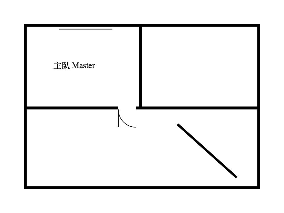
In code order:
1. Thresholding: each pixel is marked dark or light. A pixel at or below the brightness threshold is dark. Transparent pixels never count. The default is 145. The "Wall sensitivity" slider covers 60 to 210.
2. Sampled scanning: every few rows are scanned horizontally, and every few columns vertically. For a 960×720 image, the step is 4 px.
3. Keep long runs only: a run of dark pixels must be long enough. The minimum is about 0.45 m, and never under 12 px.
4. Grouping: runs that sit close together and overlap join one group.
5. Output: each group becomes one purely horizontal or vertical wall. Thickness comes from the group width plus the sampling step, clamped to 0.15–0.32 m. At most 120 walls are produced.
This method is basic. It does not follow a line's direction. It has no advanced line finder (such as the Hough transform). It has no text recognition and no perspective correction.
The consequence is direct. A clearly diagonal line, such as 45°, leaves only short runs on each row. Those runs fail the length check, so the line is missed. Walls tilted by only a few degrees behave differently; see "scan skew" below.
We tested this with a synthetic 960×720 image. We called the vectorizer directly in Node on an Apple M3 Pro. It produced 7 walls in 3.8 ms (median of 10 runs):
All 4 outer walls were found.
The inner wall split into 2 parts, leaving a 0.75 m doorway.
The quarter-circle door swing was not detected.
All three 1 px window lines were missed. They fell between the 4 px sample rows.
The 45° diagonal wall was missed.
A 60×14 px black text block became a 0.75 m wall.
DXF and DWG: layer names plus parallel lines
CAD drawings usually show a wall as two parallel lines. The gap between them is the wall thickness. We do not read line weights. Wall detection relies on two things.
First: layer names.
Layers named like wall, 牆, 隔間 (partition), 結構 (structure), or 外牆 (outer wall) count as walls. CAD's default layer "0" also counts.
Layers named like text, 文字, 室名, or room are text layers. They are checked by default.
Layers named like dim, 標註, hatch, 家具 (furniture), door, window, 門, or 窗 are unchecked by default.
Wall and text rules win. A name that matches both sides stays checked.
Layers with unclear names are checked by default.
If the checked layers contain no lines, all lines are used.
You can toggle each layer under "CAD Units & Layers."
Second: geometric pairing.
1. Lines shorter than 0.12 m are dropped first.
2. Each remaining line is classified. A line is horizontal if its ends differ by under 0.04 m vertically. Vertical works the same way. Everything else is diagonal.
3. Two same-direction lines become one wall if they are 0.07–0.38 m apart and overlap by at least 0.25 m.
4. With several candidates, the code prefers a longer overlap or a gap closer to 0.15 m. Either one triggers a switch, so the result depends on scan order.
5. The wall thickness equals the gap, clamped to 0.09–0.32 m.
6. An unpaired line becomes a 0.15 m thick wall on its own.
7. Diagonal lines are never paired. Each becomes a single 0.15 m thick wall.
These items disappear; the code does not read them:
Arcs (ARC) and circles (CIRCLE).
Block references (INSERT). A block is a reusable CAD symbol, such as a door or a toilet.
Multilines (MLINE), smooth curves (SPLINE), fill patterns (HATCH), and dimension labels (DIMENSION).
DXF also skips the old POLYLINE + VERTEX form.
This one stays, but changes shape:
Arc segments inside polylines become straight lines.
Pairing checks each line against the others, so cost grows with the square of the line count. A DXF with 10,000 lines (561 KB) produced 5,000 walls in 90 ms. That was in Node on an Apple M3 Pro, median of 3 runs.
4. What we cannot do
Doors and windows
None of the four formats detects doors or windows. You cannot place them by hand either.
A gap in the wall lines becomes a full-height opening. The 3D view has no door heads and no window sills. Walls read from your file are all 1.98 m high. The extra outer frame the tool adds is 2.72 m, lowered to 1.18 m on the two camera-facing sides.
Door openings in outer walls get sealed. The 3D scene adds a ring of outer walls along the outline. The outline is the bounding rectangle of all walls. That ring covers any door gap in an outer wall.
Only 13 furniture types can be placed. Doors and windows are not on the list. Walls cannot be edited in 3D.
Per format:
Images and PDFs: door swings are too thin and short, so the length check removes them. Window lines are thinner. They may vanish, merge into a wall, or become a wall. It depends on line weight, darkness, and whether a sample row hits them.
DXF and DWG: door swings (ARC) and door or window blocks (INSERT) are not read. Layers named with door, window, 門, or 窗 are unchecked by default. While those layers stay unchecked, their door-leaf lines do not become walls.
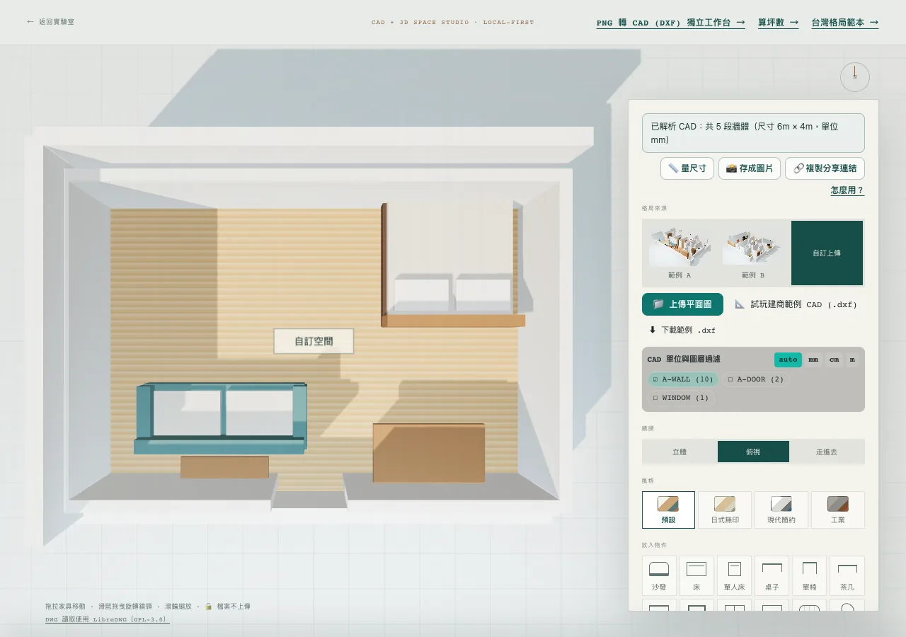
This is layer filtering by name, not door or window detection. Door and window lines still become walls in these cases:
The layer name is not on the list. One example is A-GLAZ, the window layer in the AIA layer standard.
The name also matches a wall or text rule, such as 外牆門窗 ("outer wall doors and windows").
The checked layers contain no lines, so the tool falls back to all lines.
Diagonal and curved walls
| Item | Images and PDFs | DXF and DWG |
|---|---|---|
| Diagonal walls | Missed | Kept as a single wall, 0.15 m thick, not paired |
| Curved walls | Missed | Arcs and circles dropped; polyline arcs straightened |
Multiple floors
PDFs: page 1 only.
CAD files: every entity lands on one plane. There is no floor concept and no layout-tab handling.
Perspective from phone photos
Not tested. We have no samples, and the code has no perspective correction.
From the code, we expect mild distortion to be straightened, like scan skew. Strong distortion may break lines into short runs that get filtered out.
We did test scan skew. We made a separate synthetic image (an outline plus one inner wall with a doorway). We rotated it from 0° to 5° and parsed it. Every angle gave 6 walls, with almost the same total length. But every output wall is forced horizontal or vertical. By geometry (not measured), a 10 m wall skewed 5° shifts about 0.44 m at each end. Real scans with noise and shadows are not tested.
Other limits
The outline is always a rectangle. An L-shaped plan becomes a box. For CAD files, the minimum outline is 5 m × 4.4 m.
Dark dimension lines may become walls. Light gray ones are filtered out.
Some AutoCAD 2000 DWG files cannot be read. Section 6 explains why.
5. Scale and units
DXF and DWG: file unit first
With the unit set to "auto," the tool first reads $INSUNITS from the file header. $INSUNITS is the CAD field that stores the drawing unit.
If it says mm, cm, or m, the tool uses it.
Otherwise (for example inches or "unspecified"), or if it is missing, the tool guesses from size. It takes the largest span of all lines on checked layers (width or depth, whichever is larger). Over 1800 means mm. Over 45 means cm. Anything else means m.
You can switch between auto, mm, cm, and m. A manual choice always wins.
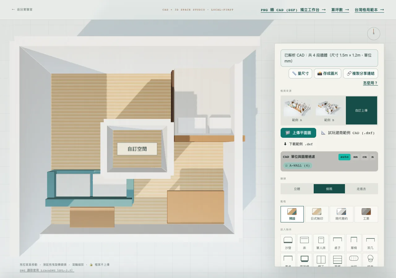
The size guess can be wrong. Take a 1.5 m × 1.2 m room drawn in mm. Its largest span is 1500, which is under 1800. So the guess is cm, and the room becomes 15 m × 12 m. If $INSUNITS says mm, the tool gets it right.
Images and PDFs: click a wall you know
Images have no units. After walls appear, a scale dialog opens:
1. Click one end of a wall with a known length.
2. Click the other end. Both ends can be dragged. A 3× magnifier appears above your finger while dragging.
3. Type the length. You can pick cm or m, or type "3.6m" or "360公分" directly. Full-width digits work too.
4. Press "Apply scale." The tool extracts the walls again with the new scale.
How the math works: real length ÷ pixel distance gives meters per pixel. Multiply by the image's pixel width to get the plan's real width.
Example: the wall you clicked is 3.6 m long and spans 300 px. The image is 960 px wide. The plan is 3.6 ÷ 300 × 960 ≈ 11.5 m wide.
The length you enter must be between 30 cm and 100 m. If the two points are under 10 px apart, no scale is set.
You can also enter the real width of the whole plan. If you choose "Skip for now," the default image width of 12.0 m stays.
6. Pitfalls
LibreDWG, our DWG parser
We read DWG with LibreDWG, a GNU DWG library written in C. We use @mlightcad/libredwg-web 0.8.0, which compiles it to WASM. It now loads through the Worker shipped with @mlightcad/libredwg-converter 3.15.11 by the same author.
1. Version one loaded from a CDN at runtime. It was not in the project's package list, and it was never tested. We had no sample files, so DWG reading was never verified. We removed that code.
2. We now self-host a pinned version. The parser ships with the site, not from a CDN.
3. 0.8.0 cannot read the AutoCAD 2000 sample file. It fails with memory access out of bounds inside LibreDWG's C decoder. Our conversion code never starts. We did not patch the package. The page FAQ says some AutoCAD 2000 DWG files may not load.
4. A crashed WASM instance is unusable, and it starts with 1 GB of memory. So each upload gets a new Worker, which is closed after parsing.
5. The package does not export its wasm path. Our first version used a bundler alias to reach it. After we switched to the upstream Worker files (see the next section), we removed the alias.
6. The npm package has no license text. We host the full GPL-3.0 text on our site.
How big is the parser? Read both numbers.
File size: 10.8 MB. This is the .wasm file itself.
Transfer size: about 1.8 MB. The live site serves it with brotli compression.
The server response sets a one-year cache lifetime, marked immutable.
We timed "file picked to result shown" on the live site on 2026-10-18. We used Playwright with headless Chromium and a cold cache each round. The sample was a LibreDWG test file (149 KB). It is not an architectural floor plan.
| Scenario | First pick (includes parser download) | Second pick, same page |
|---|---|---|
| Desktop, no throttling (3 runs) | median about 0.7 s | about 0.15 s |
| Desktop, 20 Mbps, 40 ms latency (3 runs) | median about 1.3 s | about 0.15–0.19 s |
| Simulated phone, 4G 1.6 Mbps, 150 ms latency, 4× CPU slowdown (1 run) | about 9.9 s | about 0.24 s |
We believe the second pick is fast because the parser comes from the browser cache. We did not see a direct "from cache" flag, so this is an inference. Safari and Firefox are not tested.
GPL-3.0: how we isolate it
LibreDWG is licensed under GPL-3.0. Here is how we isolate it:
The Worker and .wasm are the upstream author's original files. We deploy libredwg-parser-worker.js and libredwg-web.wasm from @mlightcad/libredwg-converter 3.15.11, without changing a single byte. Their SHA-256 hashes match the package files, so anyone can download and compare them.
None of our code is inside the Worker. The page only sends the file through postMessage and receives the parse result. It does not import any JavaScript from the package. We wrote the message types ourselves.
The main bundle contains no LibreDWG code, only the Worker URL string.
It downloads only when you upload a DWG. Opening the page, or uploading DXF or PNG, does not fetch those files.
The page also shows the line "DWG reading uses LibreDWG (GPL-3.0)." It links to a license note with the version, source, and commit. The note also states that we did not modify the package.
Our first version was different. We wrote our own Worker that called LibreDWG directly. While writing this article, we reread the Free Software Foundation's GPL FAQ and switched to the setup above. The upstream author uses the same structure in his own product to keep the GPL parser apart from the main app. After the switch, all 6 DWG samples parsed to byte-identical results.
This section describes the technical setup only.
A blank page when WebGL fails
In the old version, the whole page vanished when WebGL was unavailable. No heading, no text. Creating the 3D scene threw an error, and React unmounted the entire page.
The fix:
1. Wrap scene creation in try/catch and record the failure.
2. Show a notice card in the header, with links to tools that do not need 3D.
3. Disable all 3D-dependent buttons at once.
4. Skip parsing uploads, and skip the DWG parser download.
There was a small trap too. The first notice card sat in the 3D canvas layer. The hero image covered it, so nobody could click it. That layer used position: fixed, which gives it its own stacking order in CSS. No setting on the card could lift it above the image. We moved the card into the header, in the normal page flow.
Not handled yet: WebGL failing mid-session.
The hero video and LCP
LCP (Largest Contentful Paint) is a Google loading metric. It measures when the largest above-the-fold element is drawn.
The tool page has a demo video at the top. Version one autoplayed after page load. We measured a slower LCP on the live site and reverted. We could not reproduce the slowdown locally. The cause is still unconfirmed.
Version two plays only on click:
The preview uses <img>, not <video poster>. With <video poster>, the LCP element counts as the video element.
A click is user input. After user input, the browser stops recording LCP. So a <video> added after the click cannot become the LCP element.
After version two went live, we found a bug: mouse clicks failed, but the keyboard worked. A parent container had pointer-events: none. The video frame inherited it, so clicks passed through to the 3D canvas below. The fix was pointer-events: auto on the video frame itself.
Why did our acceptance script miss it? It triggered playback only with the Enter key. Keyboard input ignores pointer-events, so the check passed. We added a real mouse-click check. Reverting the CSS now makes that check fail.
Measurement has its own trap. When we measured this page's LCP, headless Chrome needed a GPU. We use Metal on macOS. With software rendering (SwiftShader), LCP came seconds late, so we discarded that round.
Smaller pitfalls
DXF files exported by the tool gain extra walls when re-imported. Each exported wall has a center line, two face lines, and two end caps. On re-import, the center line and caps each become walls. We have not checked how much this shows in 3D.
Playwright request interception disables the HTTP cache. Our first "second pick" timings were wrong because of it. We discarded that round.
PDFs render at about 2000 px, then shrink to 960 px. Part of that work is wasted. This is inferred from the code; the impact is not measured.
pdf.js has no font data path set. Text without embedded fonts may not render. Wall lines are usually unaffected.
7. Three bugs found in review and fixed the same day
Before writing this article, we checked each claim on the page against the code. Then we tested real uploads. We found three problems and fixed them the same day.
1. DXF ignored the file unit
The page said "DWG and DXF use the units in the file." Only DWG did. DXF always guessed from size. So the 1.5 m × 1.2 m room from section 5 became 15 m × 12 m.
Fix: DXF now reads $INSUNITS too, with the same rules as DWG. After the fix, that file reads as mm, at 1.5 m × 1.2 m.
2. The underlay did not line up with the walls
After an image upload, the original plan sits semi-transparent on the floor as an underlay. Before the fix, its black outer walls sat inside the 3D outer walls.
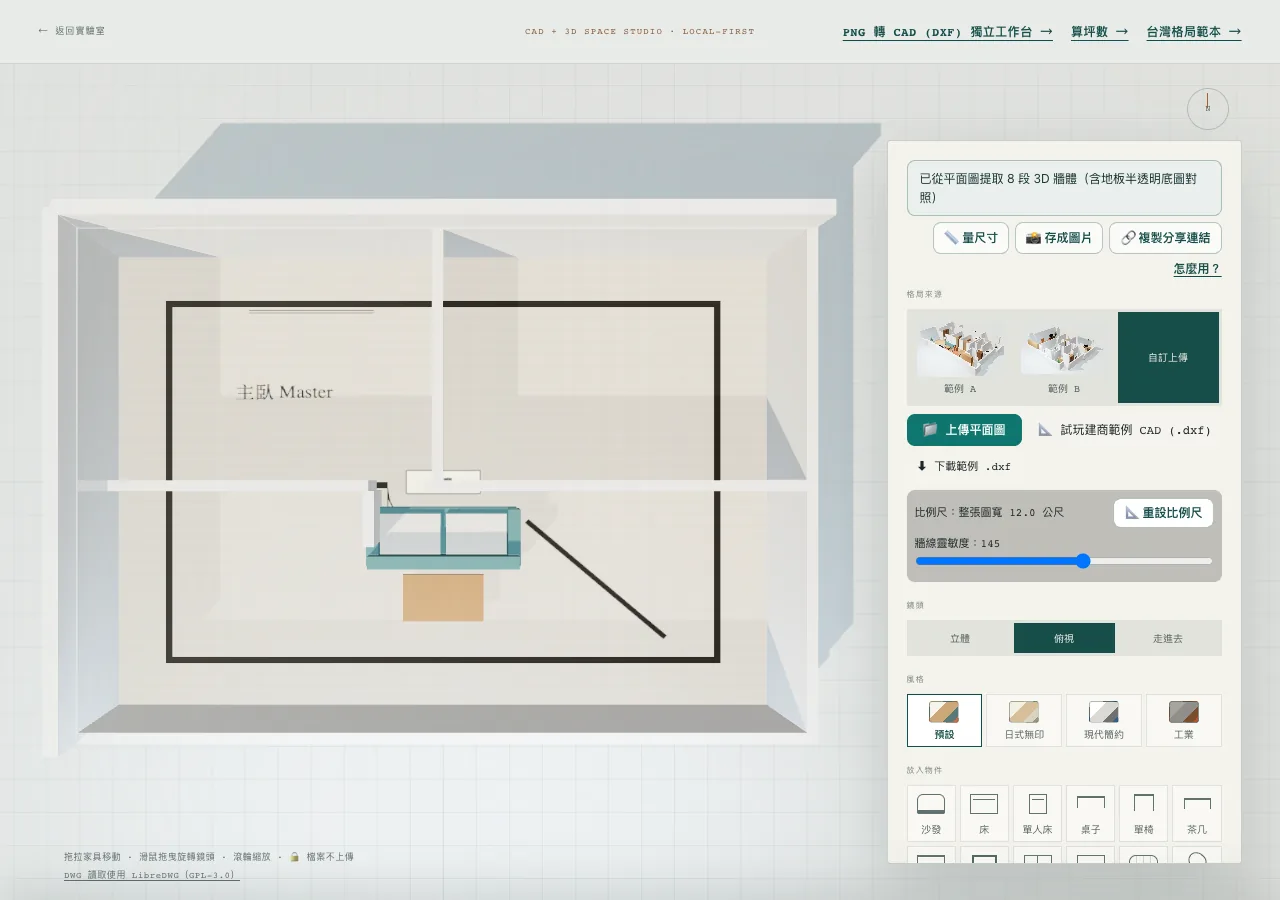
Cause: the code stretched the whole image, white margins included, onto the bounding box of detected walls. Any margin shrank the underlay.
Fix: parsing already centers the image at the origin. So the full image extent is pixels × meters per pixel. The underlay now uses that extent. The underlay and walls share one scale, so they resize together.
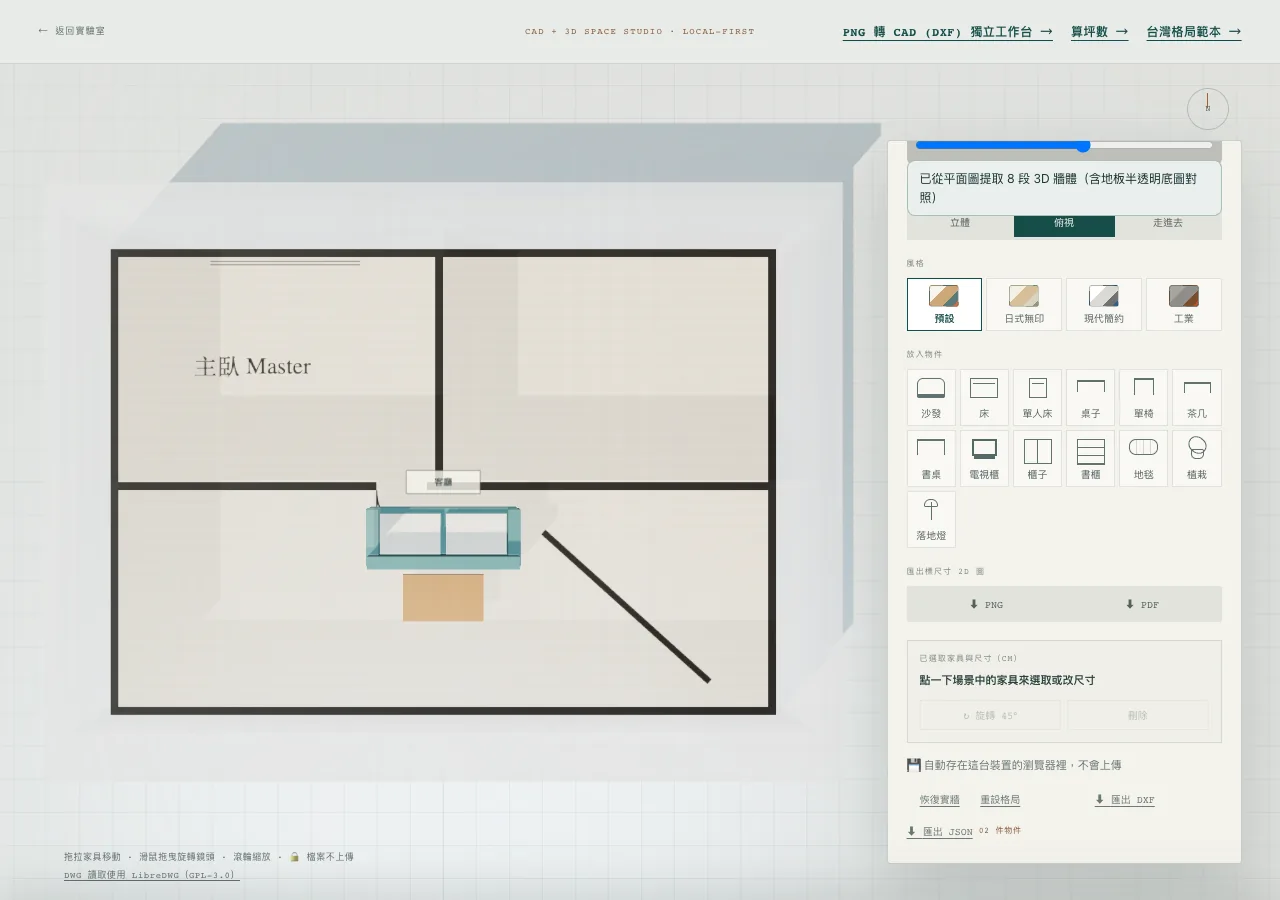
This bug only affected the underlay display. Wall positions, scale, and measurements were unaffected by it.
Still open: layouts sent from the "PNG to CAD (DXF) Vectorizer" still use the old stretch.
3. Door and window layers became walls
Before the fix, door and window layers were checked by default. A door-leaf line became a wall that blocked the doorway.
Fix: door, window, 門, and 窗 were added to the unchecked-by-default list. On the same test drawing, walls dropped from 8 to 5. The bottom wall now shows a 0.9 m opening. You can still re-check those layers by hand.
Again: this filters layers. It does not detect doors or windows.
How we verified
We added 8 unit tests. All 94 tests passed at the time (2026-10-18). Three of the new tests fail on the old code.
In local headless Chromium, we uploaded PNG, PDF, DXF, DWG, and 2 new DXF samples. Page errors were zero.
We checked the underlay by screenshot. With "X-ray walls" on, the walls turn semi-transparent. The black plan lines and the wall bases overlap.
8. Next steps (under consideration, not promised)
Stop adding the outline wall ring for uploaded layouts, so outer door gaps survive.
Add common window layer names such as A-GLAZ to the unchecked-by-default list.
Make layouts from the "PNG to CAD (DXF) Vectorizer" use the full image extent for the underlay.
Handle WebGL failing mid-session.
These are still being evaluated. There is no timeline.
Open the 3D layout lab and upload your planPrevious: turning a floor plan into a 3D space you can walk into